Freedom—August 18, 2020—I arrived at the Dam site just as the second gate was about to be unloaded from the truck it arrived on from the fabricator in Massachusetts. This sequence of photos shows the gate being hosted into place. The entire process lasted almost two hours due to the tolerances between the concrete piers, which is about 1/4″. Once bolted in place, the gate was lowered to its open position, then raised to check the alignment.
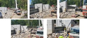
The photo below shows the #2 gate in its lowered position as the installation team from Charter Construction adjusted and checked the alignment of the gate. It was then raised to its up position, and the four support braces were raised into place. When the dam is in operation, these will be stored in the new headhouse. The dam gates will then be raised and lowered by hydraulic actuators mounted on the top of the concrete side walls.
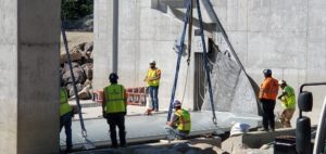
The following 2 photos show the support braces in place, on the downstream side of the dam.
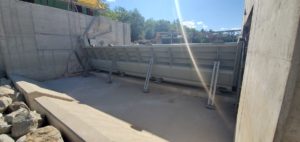
The 4th photo shows the bracket with shackles which will hold the dam in the closed position during the normal high-water setting. There is one of these at each end of the gate. The conduits pictured feed power to the plate heaters, which keep the side plates from freezing up in the wintertime. The side plates are the surface on which the gate end rubber seals ride when the gate is activated. This keeps the water from seeping past the sides of the gates. There is a similar seal positioned at the bottom of the gate to prevent water from seeping under the gate. These seals are made of very thick rubber attached to a steel plate.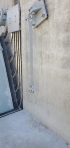
All gate steel components are coated with a very sophisticated paint to prevent corrosion of the steel. The end plates which the side seals ride on are made of stainless steel. The recesses in the concrete where the conduits run will be grouted with a very high strength concrete grout.
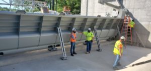
The 5th photo shows the upstream side of the gate. You can clearly see the gate bottom seal in this photo, which is a one-piece continuous rubber and steel seal bolted to the bottom of the gate. The steel plates, with eyes on the face of the gate, are used to hoist it into place. These will remain and can be used if and when the gates need to be removed and replaced many years from now. At the far end of the gate, you can see the conduit runs and the sealed junction box for the electrical wiring for the plate heaters. The hydraulic actuators, are arriving on site next week, and will mount on top of the two end walls, one for each gate, and will be connected to each gate with a huge steel arm, which when activated, will raise and lower the gates as needed.
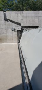
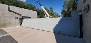
Upstream from the gates, positioned in the base slab, will be a series of steel I-beams mounted vertically, which will allow temporary placement of the drop boards to hold the water back during times when the dam gates require servicing or maintenance. The tops or these I-beams will be attached to the new catwalk structure, extending across the top of the concrete walls the entire width of the dam.
The 6th photo is the upstream face of Gate #1, previously installed. On the far right end of the gate you can see the raised section, with the shaft where the hydraulic actuator arm will attach. The black mats on the base slab are temporarily covering the recessed mounting holes for the vertical I-beams which will support the drop boards. On the face of each concrete wall are formed slots to receive the ends of the drop boards which are lowered down in place from the catwalk overhead.
The 7th photo shows the new head house situated beyond the end wall. It will house, in two separate rooms, a propane powered generator and the hydraulic pump. The generator will provide emergency power to the hydraulic pump in the event of a local power outage. The hydraulic pump will provide hydraulics to the actuators operating the lowering and raising of the two gates.
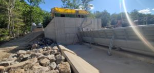
The head house will be finished with cedar clapboard siding and a standing seam metal roof. The two interior spaces will each have their own entry door and will be accessed by stairs and an elevated catwalk, which will be connected to the dam catwalk. The generator is already installed in the head house and the hydraulic pump and associated equipment will be installed soon.
To the left of the head house, set further back from the dam, is the concrete platform supporting the propane tanks supplying fuel to the generator. Safety railings and access stairs will be installed on this platform.
Additionally, the rip rap stones will be installed similar to that pictured (where the temporary access ramps are currently located downstream from the new dam structure) for crane access during the construction process. This may remain in place to facilitate the demolition and removal of the old dam upstream from the new dam. A temporary dam will also be constructed upstream from the old dam to facilitate its removal, providing a safe and water-free environment for the crew removing the old dam.
Editor’s note: Timothy Otterbach is an Ossipee resident and a member of the Ossipee Lake Alliance board of directors.

When this is all completed,hope there will be an open house…Thanks for the pictures….
Thanks for a terrific report and pics!
Thanks for your clear description of the progress on the dam. It has been a pleasure reading your updates. Just one question – is this a top release or bottom release structure?
Great pictures, very interesting and informative of what the scope of the project is and just how it will function in the future.
Newly joined the alliance and wondering when the lake will be lowered after Labor Day 2020.